|
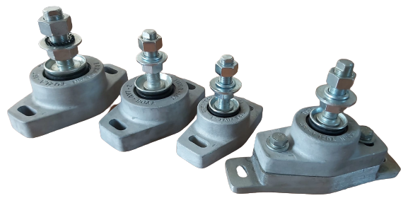
ALUMINUM BODY VIBRATION WEDGES ( 1 - 1A - 2 - 2A - 2B - 3 )

Sub connection vibration mounting with adapter
ALUMINUM CONSTRUCTION VIBRATION CHOCKS
ALUMINUM CONSTRUCTION VIBRATION CHOCKS
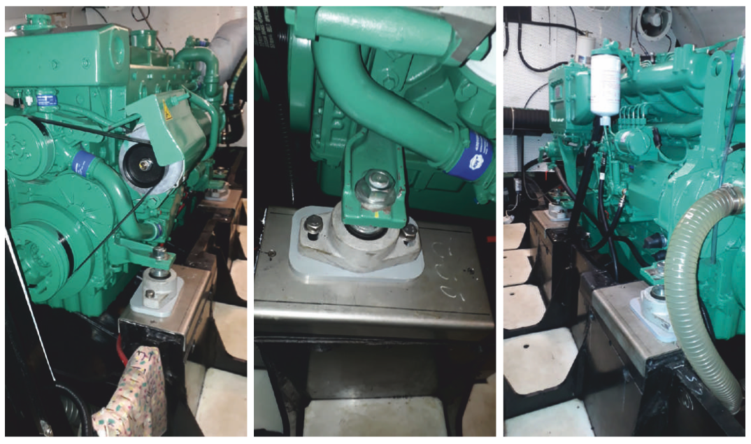
So far vertical mount rubber chocks have been made as vibration suooressors; that is, te efforts have been directed to eliminate the vibraions generated by a free-standing engine. But with the ERMAKSAN made marine products, the entire propulsive power of the engine (propeller) is born by the engine mounting chocks (blocks). Because ERMAKSAN vibration chocks are designed for forward, backward, upward and downward forces, they minimize the vibrations for each position. Therefore, they are used for other apllications than marine use as well (generators, compressors etc.). The types selectable according to the weight of the engine are given in the table below.

| 1 |
ALUMINUM BODY |
| 2 |
CENTER RUBBER BUSHUNG |
| 3 |
OIL COLLECTION BOWL SHEET |
| 4 |
CONNECTION SHAFT |
| 5 |
ENGINE ADJUSTING NUT |
| 6 |
RUBBER FEEDING-STRAIGHT WASHER |
| 7 |
ENGINE MOUNTING FOOT |
| 8 |
NETHER RUBBER CONNECTION BOLT |
| 9 |
WASHER |
| 10 |
SPRING WASHER |
|
TYPE
|
A
|
B |
D |
E |
F |
G
|
H1
|
mm(L)inch
|
POZ 8
|
SHORE
|
Z
The amount of stretching in 3 mm
|
WEIGHT kg
CHOCK WEIGHT
|
| AVT 1 |
139 |
68 |
M16x1.5 |
28 |
12,5 |
22 |
70 |
100 |
4" |
M10x20 |
50 |
150/3 |
0,850 |
| AVT 1A |
139 |
68 |
M16x1.5 |
28 |
12,5 |
22 |
70 |
100 |
4" |
M10x20 |
65 |
300/3 |
0,850 |
| AVT 2 |
165 |
96 |
M16x1.5 |
35 |
13 |
25 |
75 |
133-*127 |
5 ¼-5" |
M12x20 |
65 |
500/3 |
1,580 |
| AVT 2A |
165 |
96 |
M18x1.5 |
35 |
13 |
25 |
75 |
133-*127 |
5 ¼-5" |
M12x20 |
65 |
500/3 |
1,580 |
| AVT 2B |
165 |
96 |
M20x1.5 |
35 |
13 |
25 |
75 |
133-*127 |
5 ¼-5" |
M12x20 |
65 |
500/3 |
1,580 |
| AVT 3 |
183 |
104 |
M24x2 |
33 |
16 |
27 |
90 |
140-*127 |
5 1/2"-5" |
M14x25 |
70 |
800/3 |
2,120 |
Z: According to weight / avarege stretchching quantity (kg/mm)
|
|

ALUMINUM CONSTRUCTION VIBRATION INSULATOR (3A-4-4A-5-6)
AVT (3A-4-4A-5-6) are the vibration insulators that able to carry more loads with respect to other models (AVT 1-1A-2-2A-2B-3) and when they are placed under the machines in the marines, with the No. 5 tool (motor adjuster nut), it is very easy to make any required adjustments.
In these models, during the montage, it is also possible to use No. 9 pivot nut to tighten, during the disassembly it does not need any lifter to be lifted as well and they become available for re-montage again.
Our insulators are being produced in a variety of rigidities (Shore A). The deformation, vibration and oscillations of the insulator that it will be subjected to load, of course, will differ with accordance to the rigidity of the insulator. In marine type of motors, it is not wanted the motor’s exposition to vibration since it will harm the shaft, gear housing and bearing.
The Selection of Vibration Insulator: In marine type motors, 1HP refers to 10 Kg (98,1N) as a repelling force. That value is close to 13 kg/HP in tugboats.
For instance: The type of insulator and numbers of it to be used in 200HP Marine motors;
The repelling force of 200HP motor (approximately)= 200HP x 10 Kg = 2000 kg
The type of vibration insulator that is required = 2000kg/4insulators = 500 kg/insulator
That means, for the result, according to Z values, AVT-2 is the vibration insulator that we should use. In such values security coefficient of our insulators is 2-3. For greater values, numbers of insulators may increase to 6 or 8.
Values of forces can be transformed to Newton. 1kg=9,81N , 1000N=1kN.
For detailed information, please contact us.


| 1 |
ALUMINUM BODY |
| 2 |
CENTER RUBBER BUSHUNG |
| 3 |
OIL COLLECTION BOWL SHEET |
| 4 |
CONNECTION SHAFT |
| 5 |
ENGINE ADJUSTING NUT |
| 6 |
RUBBER FEEDING-STRAIGHT WASHER |
| 7 |
ENGINE MOUNTING FOOT |
| 8 |
NETHER RUBBER CONNECTION BOLT |
| 9 |
CONNECTION STUD |
| 10 |
WASHER |
| 11 |
SPRING WASHER |
|
TYPE
|
A
|
B |
C |
E |
F |
G
|
mm(L)inch
|
H1 min. |
H1 max. |
Z |
SHORE
|
POZ8
|
POZ9
|
WEIGHT kg
|
| AVT -3-A |
210 |
117 |
- |
36 |
18 |
29 |
160 |
6 1/2" |
100 |
115 |
900/3 |
A-70 |
M16X30 |
M24X2X100 |
3,300 |
| AVT-4 |
235 |
135 |
- |
38 |
19 |
30 |
180 |
7 1/8" |
110 |
125 |
1200/3 |
A-70 |
M20X30 |
M24X2X110 |
4,450 |
| AVT-4-A |
260 |
145 |
- |
38 |
21 |
30 |
200 |
7 7/8" |
120 |
135 |
1800/3 |
A-70 |
M20X40 |
M24X2X120 |
5,570 |
| AVT-5 |
310 |
185 |
60 |
36 |
19 |
35 |
250 |
9 7/8" |
150 |
165 |
2500/3 |
A-70 |
M24X40 |
M30X2X140 |
10,200 |
| AVT-6 |
375 |
250 |
70 |
40 |
22 |
38 |
300 |
11 7/8" |
185 |
210 |
4000/3 |
A-70 |
M27X50 |
M36X3X160 |
17,200 |
Z: Acording to weight / avarage stretching quantity (kg/mm)
Note: AVT 3-A / AVT 4 / AVT 4-A Models can be connected with bolts with bold system.

|


